

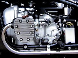
• Setting points on Ural M models
Remove spark plugs for easier engine rotation.
Open front cover & remove the distributor cap.
Rotate crankshaft until the rotor lock screw is accessable via the cutout in the distributor body.
Loosen lock screw, turn rotor slightly counterclockwise and remove.
If necessary turn the crank until the upper point is resting on the top edge of the raised area of the shaft. There are two screws in the lower contact point: the topmost is a lock screw and the lower one is the adjustment screw.
Loosen the lock screw with a short handled screwdriver. Clean point contact surfaces with emory paper if required.
With the manual advance set open (lever full forward), turn the adjustment screw to set a 0.5mm (0.0196") gap between the points. Tighten the upper locking screw securely. Turn the crank over a few times and re-check the gap until you are satisfied that the points are not slipping.
Locate the advance stop lock screw on the lower right side of the distributer housing. Loosen the lock nut and back out the screw until the tip is flush with the inside of the housing lip.
Slowly retard the timing lever, rotating the points downwards on the shaft until the gap reaches 0.4mm (0.0157"). (BE SURE that the upper points remain on the raised area of the shaft when adjusting the gaps!) Turn in the stop lock screw until the tip is set firmly against the timing plate stop and tighten the lock nut.
Saturate the felt pad with a few drops of clean engine oil. Adjust the plate tension screws (spring tensioned screws located at top left and lower right quadrants of the points plate) and advance lever so that the rotation of the plate is smooth and firm.
Inspect and clean the rotor contacts if necessary and replace the rotor on the shaft tightening it carefully.
Inspect and clean the distributor cover contacts.
• Ural Shifter Adjustment Procedure
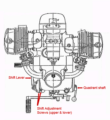
The shift pedal and the shift quadrant are separated by a ratchet assembly which allows you to press on the same lever three times to go through four gears. The actual shift indexing is accomplished by a detent ball which "drops" into detents on the shift quadrant. To keep it in third gear, you must adjust the stops so that the shift properly engages the detent.
The design of the transmission lends it to a "press and hold" type of gearchange. Toe shifting a URAL box is a surefire way to incur lots of missed shifts, so PRESS the box into gear with your heel, and HOLD the shift for a second to insure the detent and the quadrant actually find each other.
Because the adjustment is actually on the shift lever side rather than the detent side you have to put a wrench on the quadrant shaft sticking out of the right side of the transmission for adjustment.
To adjust:
- Back out both adjustment screws until 3 threads are showing.
- Take the bike for a ride to determine which gear it pops out of, and whether it pops out on an upshift or downshift.
- Assuming this is a third gear problem on upshift; put the bike in third, and set it where you can rock it back and forth a bit
- Place a wrench on the quadrant shaft and try to turn it either way. You should be able to feel the quadrant drop into the detent.
- If the quadrant drops into the detent as you turn the shaft CLOCKWISE, then turn the BOTTOM adjustment screw OUT 1/4 turn. This gives the shifter a little more travel.
- If the quadrant drop into the detent as you turn the shaft COUNTERCLOCKWISE, then turn the BOTTOM adjustment screw IN 1/4 turn. This gives the shifter a little less travel.
You may repeat this in the other gears, but indexing the worst-case gear usually takes care of the problem across all gears. If the problem occurs on a downshift, then adjust the TOP adjustment screw instead.
• Side Valve Adjustment Procedure: M72, K750
»Go to Top«
You'll need 2x 14 mm. tappet or "thin cheek" wrenches (normal wrenches are generally too large to fit in the enclosed space you'll be working in), a feeler gauge, and a tube of high temperature gasket sealant. Now, here's a cutaway of the valves:
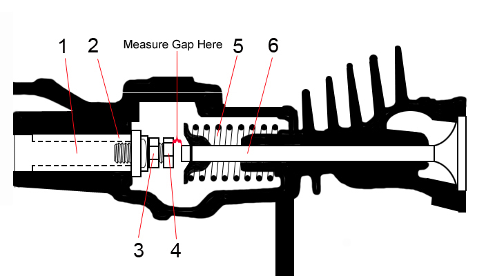
On each cylinder the intake valve is located on the carburetor side and the exhaust valve is next to the exhaust outlet. The relevant parts in the above diagram are:
(1) Valve Lifter (2) Lifter Guide (3) Lifter lock nut (4) Lifter Adjustment Bolt (5) Valve Spring (6) Valve Stem
Adjust the gap between the lifter adjustment bolt and the end of the valve stem: 0.15mm (0.005") for exhaust, 0.10mm (0.004") for intake.
- 1) Remove the spark plugs & valve cover plates, turn the starter over until the intake valve closes completely. At this point the lifter will be at it's furthest point into the engine and the valve spring will be extended.
- 2) On the exhaust valve on the same cylinder loosen the lock nut and adjust the lifter adjustment bolt to allow 0.15 mm gap between the valve stem & the end of the bolt. Holding the bolt in place with one wrench, tighten the lock nut.
- 3) Turn the crank over until the exhaust valve just begins to close.
- 4) On the intake valve, adjust the lifter bolt to allow 0.10 mm clearance
Repeat the same process on the opposite cylinder. Turn the crankshaft over completely and recheck the clearances, readjusting as necessary until the the required gaps are maintained.
• Balancing Russian Carburetors
»Go to Top«
If you suspect carb problems ...generally indicated by excessive backfiring, difficulty starting even with a good spark, or having your boots soaked with gasoline... there are a few things to check before you decide to start tearing things apart.
First, make sure you do have good spark and that the points and plugs are gapped properly.
Check the color of your plugs: optimally they should be a nice brown color, but in my experience that only really occurs in other peoples fantasies. Realistically they'll usually be dark, but they shouldn't be caked with carbon.
Next check your floats: cut the fuel off, pull your float bowls and make sure that the float is seated correctly and has plenty of free travel. Make sure you have good fuel flow from the tank and that it's even in both lines.
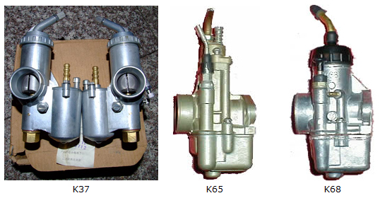
Now determine if you're running rich or lean: this is pretty much determined by your plug colors (Gray/ashy=lean, black/sooty= rich). There are at least two screen filters that need to be checked if you're lean: in the petcock (fuel tap) under the tank there will be one at the top of the bowl and / or inside the bowl. In the K37 body there's another one wrapped around the fuel port in the lower filter plug.
The rule of thumb is that if the mix adjustment is on the air intake side of the carb CW = Rich, CCW = Lean. If the mix adjustment is on the cylinder side then it's a fuel control screw and CCW = Rich and CW = Lean.
• Setting K-37/K-301/K-302 Carbs.
»Go to Top«
1. Warm up the engine (make sure both sides get hot because many times bikes are only running off of one cylinder). Retard the engine if you have manual advance. If installed, disconnect the supercharger hose and plug up the carb holes or as my lazy arse would do, pinch off the tube with vise-grips so that absolutely ZERO air passes from one side to the other. Then, kill or ground out one cylinder; we'll set the carb on the other cylinder.
2. Loosen the carb neck screws so that there is slack between the end of the cable casing and the carb neck.
3. Loosen the jamnuts on the HORIZONTAL (mixture) and DIAGONAL (slide lift) adjustments.
4. Screw the HORIZONTAL screw all the way in.
5. Set the DIAGONAL screw for minimum steady operation.
6. Adjust the HORIZONTAL screw for maximum engine speed.
7. Set the DIAGONAL screw for minimum steady operation again by backing it out.
8. Tighten jamnuts. Repeat for the other side.
9. Note differences in engine speeds when operating on single cylinders. Reconnect both cylinders. Adjust the DIAGONAL screws equally for final low speed idle operation.
10. Put it on the center stand (or jack up the drive wheels on an MT-16), fire it up, put it in 4th gear
11. Rev it up to 30-40khp, Clamp/hold the throttle in place, AND DO NOT CHANGE UNTIL THE PROCEDURE IS OVER
12. Disconnect (or ground) one cylinder wire, note exactly what the speedometer settles down to after 10 seconds
13. Now quickly re-connect that side disconnect the other (don't move the throttle even though it'll rev up some)
14. Adjust the carb cable ferrule on the running side to match the exact speed you noted while the first side was running.
• Setting K-68 Carbs.
»Go to Top«
1. Warm up the engine (make sure both sides get hot because many times bikes are only running off of one cylinder). Retard the engine if you have manual advance. If installed, disconnect the supercharger hose and plug up the carb holes or as my lazy arse would do, pinch off the tube with vise-grips so that absolutely ZERO air passes from one side to the other. Then, kill or ground out one cylinder; we'll set the carb on the other cylinder.
2. Loosen the carb neck screws so that there is slack between the end of the cable casing and the carb neck.
3. Note that it is now VERTICAL (mixture) and HORIZONTAL (slide lift) adjustments.
4. Screw the VERTICAL screw 1.5 turns out from a softly seated, fully in position (if already idling at all, skip this step).
5. Set the HORIZONTAL screw for minimum steady operation.
6. Adjust the VERTICAL screw for maximum engine speed.
7. Set the HORIZONTAL screw for minimum steady operation again by backing it out. Repeat for the other side.
8. Note differences in engine speeds when operating on single cylinders. Connect both cylinders spark plug cables. Adjust the HORIZONTAL screws equally in 1/8 turns for final low speed idle operation.
9. Put it on the center stand (or jack up the drive wheels on an MT-16), Fire it up, put it in 4th gear
10. Rev it up to 30-40khp, Clamp/hold the throttle in place, AND DO NOT CHANGE UNTIL THE PROCEDURE IS OVER
11. Disconnect (or ground) one cylinder wire, note exactly what the speedometer settles down to after 10 seconds
12. Now quickly re-connect that side disconnect the other (don't move the throttle even though it'll rev up some)
13. Adjust the carb cable ferrule on the running side to match the exact speed you noted while the first side was running.
• Setting K-63/K-65 Carbs
»Go to Top«
1. Warm up the engine (make sure both sides get hot because many times bikes are only running off of one cylinder). Retard the engine if you have manual advance. If installed, disconnect the supercharger hose and plug up the carb holes or as my lazy arse would do, pinch off the tube with vise-grips so that absolutely ZERO air passes from one side to the other. Then, kill or ground out one cylinder; we'll set the carb on the other cylinder.
2. Loosen the carb neck screws so that there is slack between the end of the cable casing and the carb neck.
3. Note that both adjustments are vertical screws. It's now LOWER (mixture) and UPPER (slide stop) adjustments.
4. Screw the LOWER screw 1.5 turns out from a softly seated, fully in position. (If the bike is already mostly running, it is not necessary to "pre-set" this screw, simply adjust when you get to Step 6.)
5. Set the UPPER screw for minimum steady operation.
6. Adjust the LOWER screw for maximum engine speed.
7. Set the UPPER screw for minimum steady operation again. Repeat for the other side.
8. Note differences in engine speeds when operating on single cylinders. Reconnect both spark plug cables. Adjust the UPPER screws equally in 1/8 turns for final low speed idle operation.
9. Put it on the center stand (or jack up the drive wheels on an MT-16), Fire it up, put it in 4th gear
10. Rev it up to 30-40khp, Clamp/hold the throttle in place, AND DO NOT CHANGE UNTIL THE PROCEDURE IS OVER
11. Disconnect (or ground) one cylinder wire, note exactly what the speedometer settles down to after 10 seconds
12. Now quickly re-connect that side disconnect the other (don't move the throttle even though it'll rev up some)
13. Adjust the carb cable ferrule on the running side to match the exact speed you noted while the first side was running.
• Notes & Misc. M72 Sidevalve Engine Settings
»Go to Top«
Ignition Points Gap settings: 0.40 - 0.50mm (set with advance off)
Spark Plug Gap settings: 0.50 - 0.60mm
Piston Clearance: 0.077mm (Note: pistons are oval. See Piston, Rings and Cylinder Bore Tolerances Diagram)
Piston Ring Gap: bore diameter x .004" (0.11 mm)
SAE to M Class Oil:
SAE30 = M10D
SAE40 = M16D
SAE50 = M20D
The smaller the part the more likely it is to be immediately attracted to the least accessable area of the garage floor.
CVK
Charlie's Vintage Kustoms specializes in the restoration and modification of pre- 1990's motorcycles, especially Russian Ural and Dnepr models. We also modify and repair classic Japanese, American, German and British motorcycles and assist in sourcing hard to find parts. Hours available by appointment only; located on the Black Sea Coast in Varna, Bulgaria. Please contact us for further information.

Visit our blog at Flesh and Relics or find us on FaceBook
This is and will remain a free resource, but if you have a couple of bucks, euro, dinar or free range chickens to spare you can direct them towards a good cause here: